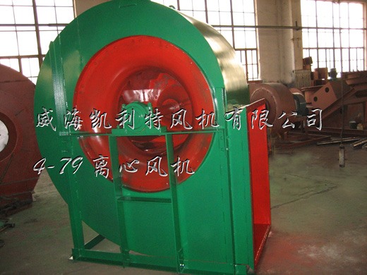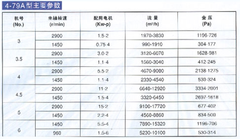
The 4-79 centrifugal fan can be used for indoor ventilation in general factories and large buildings. It can be used to transport gas and output gas. The type of conveying gas is air and other unnatural, harmless to human body, and non-corrosive to steel materials. The gas does not contain viscous substances, and the dust and hard particles contained are not more than 150mg/m3. The temperature of the gas must not exceed 80°C.
2. Type
The fan can be made into two forms: clockwise rotation and counterclockwise rotation. When looking at the fan from one end of the motor, the impeller rotates clockwise, which is called a clockwise fan, which is represented by "clockwise"; when it rotates counterclockwise, it is called a counterclockwise fan. Expressed as "inverse".
The outlet position of the fan is expressed by the angle of the air outlet of the casing. Type 4-79 fans No. 3~12 are all made into a form when leaving the factory, and the user can install it in the required position according to the requirements. No proof is required when ordering. №3 The adjustment range of the air outlet position is 0°~225°, the interval is 45°. №3.5~6 The air outlet position adjustment range is three angles 0°~225°, the interval is 22.5°, the transmission mode of №3~6 is A-type transmission; the air outlet position adjustment range №7~8 is 0°~180°, The fan interval is 22.5°, the transmission mode of №7~8 is C-type transmission; the transmission mode of №10~20 is E-type transmission, and the position of the air outlet is made into three fixed types: adjustment range of three angles: 0°, 90°, 180°, can't be adjusted, please specify when ordering. №10~20 double air inlet types are made into three types of fixed air outlet positions: three angles of adjustment range: 0°, 90°, 180°, transmission mode is E-type transmission, which must be noted when ordering.
Three, structure
Fans No. 3 to 6 of the 4-79 type fans are mainly composed of impeller, casing, air inlet and other parts distributed with direct-connected motors; No. 7 to 20 in addition to the above parts, there are transmission group parts and so on.
(1) The impeller is composed of 16 backward-inclined arc-shaped thin-plate blades, a curved front disc and a flat-plate rear disc. They are all made of steel plates and have been dynamically balanced. They have good air performance, high efficiency, low noise, and operation. smooth.
(2) The casing is made of two different types, the casings of No. 3~12 are made as a whole and cannot be disassembled; the casings of No. 14 to 20 are made of two-open type, divided into two halves along the horizontal plane, connected by bolts .
(3) The air inlet is made as a whole, installed on the side of the fan, and the cross section parallel to the axial direction is a curved shape, which can make the gas enter the impeller smoothly with less loss.
(4) The transmission part is composed of main shaft, bearing box, rolling bearing and pulley.

Four, installation, use, and adjustment
(1) During use and debugging, excessive or insufficient flow often occurs. There are many reasons for this phenomenon. If the flow is large and sometimes small during use, it is mainly due to the resistance in the pipe network. The time is large and sometimes small, or the fan is working in the flying area; if it is in use, it gradually decreases after a long time, or suddenly decreases in a short time, mainly due to the blockage of the pipe network.
After the fan is newly installed, excessive or insufficient flow occurs during operation. The main reasons are as follows:
1) The actual value of pipe network resistance differs too much from the calculated value. It can be known from the general pipe network characteristic equation P=KQ2 that if the actual value K is less than the calculated value K, the flow will increase; if the actual value K is greater than the calculated value K, the flow will decrease.
2) The influence of the total pressure deviation △P of the fan itself was not considered in the selection. When the total pressure of the fan has a positive deviation, the flow will increase; when it is a negative deviation, the flow will decrease.
When the fan starts to run after being newly installed, or when the flow is too large or too small during use, one of the following methods can be used to eliminate it.
1) Use an adjusting device to adjust the flow rate.
2) Change the speed of the fan to adjust the flow rate.
3) Change the fan with higher or lower pressure to adjust the flow.
4) Change the resistance coefficient of the pipe network to adjust the flow rate.
It must be pointed out that: throttling devices are generally used to adjust the flow rate, but when the actual flow rate is much larger than the required flow rate, this method wastes too much power. If conditions permit, usually reduce the fan speed or change the pressure to a lower level. Fan.
When the throttling device is fully opened, the flow is still too small. At this time, the throttling device has lost its throttling effect. Therefore, try to change the pipe network to reduce the resistance coefficient to increase the flow. You can also increase the fan speed and change the pressure. High fan, but the fan connected by direct motor and coupling generally cannot change the speed. Only the fan with drive can change the diameter of the pulley to increase or decrease the speed, but the maximum speed of the fan cannot exceed the maximum speed on the performance table.

